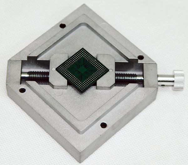
Hello, this is a short video about the fluxes that i use for BGA repairs Reballing - Rework.i have used KINGBO RMA-218, AMTECH NC-559 and 4300LF/TF, SRA TF50. The EZReball™ reballing process allows even the beginning repair technician to reliably and quickly replace spheres on a BGA package. Alignment is simple with the edges being “squared up” with the sides of the BGA. You won’t need to buy custom fixtures or frames for your bga rework.
Bga Reball Rework Machine
Reading time ( words)
Robert Avila and Wade Gay, Finetech, describe the steps to BGA rework, aided by video clips of rework in action. There are at least five steps in successfully completing the cycle for BGA rework. These steps, which include component removal, site cleaning, reballing, and soldering, do not change, independent of whether or not the BGA is on a PCB that is large, small, thin, or thick, etc.
Removing the component from the PCB is step one. Cleaning the BGA site (and PCB) follow as step two. Attaching new solder balls (reballing) is step three, and re-soldering the BGA back to the PCB is the final step. There may be others, such as single-ball reballing, that have not yet become mainstream but could add significant value. This is especially true when attempting to re-ball a BGA that has a high ball count or small ball pitch.
The BGA package has long been a mainstay in surface mount PCB designs. BGAs are able to meet equally growing pressure to decrease product size and increase functionality. Many types of BGAs are integrated into products worldwide.
Step 1: Component Removal
As components become more complicated, certain parameters need to be fully understood before attempting to remove a BGA.
Prior to removal, PCB preheating is necessary. By saturating the copper within the PCB, then applying top heat to the component to be removed, the heat becomes localized at the component and not distributed throughout the thermally conductive material of the PCB.
Figure 1. Inside the BGA.
Monitoring the PCB temperature with external thermocouples (TC) is standard practice. When heating the component from the top side, the generated heat should remain localized at that site until the solder becomes molten. Then the component is lifted from the PCB using vacuum. However, if the PCB has not been preheated (saturated), then heat generated from the top will be distributed into the PCB until the copper (thermal conductor) has been saturated. By the time this happens, the component could become unsalvageable or at least difficult to recover. These effects include the die within the BGA package exceeds threshold temperature (Figure 1); thermal mismatch between PCB and component exceeds the limits and results in delamination; heat generated from the top to liquefy the solder begins to liquefy neighboring components; and activation time for flux passes without properly transferring heat between solder and component.

Preheating the PCB efficiently is the first of several steps to successfully remove the package without compromising the integrity of the PCB or the BGA.
Typical IR heat sources traditionally require little tooling for specific BGA sizes. This approach of one tool fits all has advantages and disadvantages. Hot air rework systems, for the most part, require tooling based on component size. However, having the capability to control air flow precisely top and bottom while heating the component is critical in rework. BGA components for the most part are black on the top, to cover and protect the die within the package. When comparing the absorption/reflection ratio of IR, the middle area of the package absorbs a good portion of the energy while the peripheral areas remain cooler. Process control is difficult, and reproducibility from component to component and board to board can be an issue.
Figure 2. IR rework system concept.
On the other hand, hot air convection proves to be advantageous as the absorption of heat by the component and circuit board is essentially independent of a material’s color or texture. Additonally, inducing nitrogen to the site during component reflow has advantages. In air-atmosphere rework, an oxide layer forms around the solder sphere as it reflows. Inducing nitrogen during this step displaces the oxygen and eliminates the oxide layer forming around the molten solder. Whether or not nitrogen is used, the desired temperature and dwell times stay fixed.

Figure 3. Effects of using nitrogen during BGA rework.
As shown in Figure 3, the pads of a device appear to remain shiny when nitrogen is used, compared to the pads reworked in air.
This video shows BGA removal in an air atmosphere.
Here, a BGA is removed under nitrogen.
Step 2: Site Dressing and Solder Removal
After component removal, the next step is site cleaning, also referred to as residual solder removal. This process historically has been done off-line, typically with an operator using a hand soldering iron and copper braid. With lead-free solders entering mainstream manufacturing a few years ago, the increased melting point of the solder complicates this process further. Challenges include a lack of process controls; damage to the solder mask with excessive and uncontrolled heat; and growth of inter-metallic phases.
These issues can be avoided by using a combined method of convection and vacuum. Typically, both the BGA site and PCB must be cleaned to salvage the product. Cleaning the site can be tricky if there are components neighboring the BGA. Controlling the air or nitrogen flow rate is the most critical parameter when cleaning the PCB. There must be sufficient airflow to liquefy the solder; however, too much airflow could disrupt nearby components and necessitate more rework.
In this video, residual solder is removed during BGA rework.
Site cleaning the BGA requires fixturing to hold the component down, with the exposed solder facing up. Depending on size, vacuum from beneath the component helps keep it flat while vacuum is turned on to remove the residual solder — especially with smaller packages that have a low mass. Preheating is still a common prerequisite, so the die inside of the package is not thermally damaged by rapidly heating the solder. Once the solder is heated and begins to reflow, vacuum is used to remove the solder. Since this is considered an additional thermal cycle, the vacuum source (nozzle) should be designed so that only one pass is required to remove all of the solder from the component. Multiple passes increase the chance for damaging the package and unnecessarily heat the device for a longer period of time. Using a one-pass technique keeps the solder liquid for as little as 10–15 seconds.

Solder removal from the PCB can be more challenging when the board is fully populated with components. Because of this, controlling the flow of the air/nitrogen and the amount of vacuum to remove the solder are significant parameters. Temperature, volume of air, and vacuum must be optimized. It is realistic to remove all of the solder with one pass of the nozzle. As with one-pass over the component, this will reduce thermal stress to the PCB.
Step 3: BGA Reballing
In many cases, BGA components are either too valuable or supplies too scarce to discard after removal. Often times, they prove to be of value due to performance characteristics, as in failure analysis (FA).
Figure 4. Excess solder spheres being removed.Before new solder spheres are placed and reflowed onto the device, the site should be cleaned of excess flux and solder residue. Once prepped, the goal is to get all solder balls onto the device and reflow the solder without disturbing any of the newly placed spheres. Several methods of placing the balls onto the package have been developed. One common method is to use a stencil that has an aperture for each pad just slightly larger than the solder ball itself. This allows one solder ball to fall through the aperture onto the pad of the device. As the openings fill up, excess solder spheres are swept off the stencil to be reclaimed and used for another component later on (Figure 4).
Bga Reball Rework Runes
Pre-deposited solder paste or flux helps keep the BGA-ball spheres in the apertures while the remaining spheres are removed.
Figure 5. Re-balling a BGA, soldering step.
Once the stencil has each opening filled, the unit is reflowed using the recommended thermal cycle of the solder paste manufacturer. Again, the volume of air/nitrogen programmed should be controlled so that the small spheres remain inside the stencil during reflow. Having the correct thermal and flow management prevents moving the device from the rework system to a reflow oven (Figure 5).
In the event that one or more solder spheres did not attach to the device or were missed when filling the stencil, single ball rework is a process step that can be used to place single balls onto the device. Flow rate control again becomes a critical parameter to success.
Step 4: Component Attach/Re-soldering
Once the device has been removed and the sites cleaned and prepped, the final step is to re-solder the BGA onto the PCB using a process like that shown in Figure 6. This step should be similar to removing the device from the PCB. The main difference, now that the device is removed from the PCB, is that there is sufficient access to either print solder onto the device or PCB before the BGA is soldered.
Figure 6. Soldering process.
Solder dipping is a complementary process where the BGA is dipped into a pre-determined solder fixture. Once the spheres are dipped into solder, the device is then aligned and placed onto the PCB and soldered. There are two disadvantages in using the more conventional method of applying solder paste to the PCB: surface area of the PCB is often limited making access for a mini stencil on the PCB difficult; and pre-heating has raised the PCB’s temperature and applying solder paste to the PCB at this time can result in the solder paste wetting and causing shorts.
Conclusion
BGA rework is more than removing and replacing a known defective device. With package on package (PoP) and other emerging technologies evolving into production, BGA devices will become more complex, making their repair more challenging and demanding.
Robert Avila and Wade Gay, Finetech, Tempe, AZ, may be contacted at robert@finetechusa.com and wade@finetechusa.com, respectively.
Bga Reball Rework Vs
Share
Print

